Tuesday, 10 March 2009

Plane Wing

Aircraft Wing
In this blog I will describe the forces acting on the wing of an aircraft. The one I am going to choose is the Euro-fighter Typhoon which I saw on a trip to RAF Conningsby. The wing is of a strange design called a Delta wing but the cross section of the wing is of the same concept of any other wing. The leaf shaped style of an aircraft wing is what gives it the ability of fly. The air passing over the top of the wing has a velocity which higher than the air passing under the wing. This in turn lowers the pressure of the air passing over the wing which allows for lift. So the faster the aircraft goes the quicker the aircraft can gain altitude.
Wing Design
The wing design looks like this


The forces acting on it are
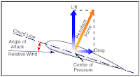


Depending on the angle of attach the lift caused by the difference in air pressure alters and the drag acting on the wing alters also. This changes the resultant force and how quickly the aircraft ascends/descends. Depending on the design of the wing alters where the centre of pressure is set, and it also affects the maximum resultant force. For example if the leading edge was much thicker then the air will pass of the wing at a much higher velocity, but the drag will also increase. So a balance has to be achieved and the wing must be altered to suit the job set for the aircraft.


Forces on a Tunnel

How could this tunnel support the massive amount of weight being applied onto it?


There is 2 possibilities to how the tunnel has been designed. It is either a semi circle of corrugated metal on top of a concrete base, or it is a pipe shape of corrugated metal throughout.

From previous work I can say that a pipe shape is very strong but it would have required more drilling when building the tunnel so I am going to assume it is the first option. Therefore the forces acting on the tunnel are as follows:
Arches are always under compression. The force of compression is pushed outward along the curve of the arch into the earth around the tunnel. This means that the actual forces on the tunnel are relatively small in comparison to the overall dissipated forces.
Matthew Dean

Bloukrans Bridge

Bloukrans Bridge


One of my examples is of a bridge i saw in South Africa a few years ago called Bloukrans Bridge. One of the attractions of this bridge is the bungee jumping stations at the centre of the bridge. However the reason i found it very interesting is because there is a pretty interesting story behind the bridge. The bridges designer spent a larger amount of his life designing this bridge since it was to become the highest single span arch bridge in the world. The bridge was built from both sides and was to be joined together in the middle, however when it came to fitting the final two pieces all the designers work was for naught since they overlapped by a few inches. The designer was so distraught that he jumped off his own bridge (without a bungee chord). What he didn't know is that the heat from the summer they were working in had made the concrete expand and in doing so put the measurements out. So when the concrete cooled down the pieces fitted together perfectly.

I bet the poor lad is spinning in his grave.

The bridge is 216m above the Bloukrans River, which also makes the bungee jump the highest bridge jump in the world (only second to the tower jump in Thailand). and has a central span of 272m, and the overall length is 451m

Forces Acting on Bridge
Arch bridges is the most natural form of bridge. In an arch bridge everything is under compression, which is what holds it up. Every section of the bridge has weight, and the compressive forces from the adjacent blocks acting on it, which is what holds it in place. If you look at the photo above you can see that the arch is holding up the rest of the structure and the supports of the road are spread evenly along the arch to give a distributed load.

Forces Acting in a Metal Step

Overview

When I went climbing in Italy I came across a large number on metal steps like the ones in the pictures which follow this overview. I would like to look into the forces acting on the step in normal use and then what would fracture the bar under unusual loading, eg. falling person, multiple people.


Forces Acting on the Step

Mass of the person / people


Force Diagram


M = Turning Force about wall
T = Force at wall
d = Distance to foot on the step
M = The mass of the person in contact with the step
G = gravity


Matthew Dean

About Me

My name is Jason Harries, and I am 20 years old. I am from Jersey, Channel Islands (no I'm not French!). I went to Victoria College for secondary school and sixth form. My first choice of University was Loughborough University, however, they would not accept me onto that course, so I ended up coming to Aston University, which to be frank was lucky because I am really enjoying myself here. I chose both universities because they both part of the DTUS programme and I was aiming to join the programme when i came here. However, due to an injury and a resulting surgery I have had to post pone the process until I can be physically tested.

I am studying Mechanical Engineering, with the hope of becoming an Engineering officer in the Royal Air Force. However as I said before that plan is being delayed until I can pass the Royal Air Forces physical examination.

Monday, 9 March 2009

Capacity of a Chairlift

I this blog I am going to be looking into chair lifts which are a vital part of the winter sports resorts as a method of transport up the mountain. The main aim i want to achieve is find out the actual capacity of a chairlift.

By studying an example in France, the Templin which is a 4 seater, I am going to work out the force on the cables between the line towers.

Specification of the Templin

  • Year Installed - 2003
  • Slope Length -1015m
  • Vertical Rise -246m
  • Speed -2.3m/s
  • Distance Between Chairs - 18.4m
  • Mass of Empty Chairs - 160Kg
  • Number of Chairs - 111
  • Primary Drive - 200KW
  • Number of Line Towers - 10
  • Cable Thickness - 40.5mm
  • Distance Between Cables - 4.9m
  • Tension at Stations - 380000N

The Hill which the Chairlift operates upon:


Things to take into account when working out the forces:

Mass of each chairlift
Mass of the cables
Mass of the passengers (only affecting chairs going up the mountain)
The forces acting on the line towers (including the turning force in the horizontal plane)

Calculations

After some calculations I have worked out that the force acting on each Tower in aproximately 10175N and 90 degrees to the slope. Although this calculations did not take into acount the affect of weather conditions such as the high winds and snow fall on the system.

Further Work

Although this result is a resonable reprisentation of the lifting system it does not take into account the high turning forces acting between the chair and cable from wind and the rocking from passengers.


Matthew Dean

Thursday, 5 March 2009

About Myself

A little about me:

Lived in Hull up to the age of 16 going through Primary and Secondary Schools. Didn't enjoy the lesions so went to Welbeck DFSC (The Defence Sixth Form College) to do my A-Levels and start my career as a Potential Officer in the British Army.

Chose to go to Aston University as one of the DTUS (Defence Technical Undergraduate Scheme) approved universities to continue my education in readiness for RMAS (Royal Military Academy Sandhurst).


Why I am doing Mechanical Engineering:

As i have grown up it has been obvious that i would move into an engineering role. Being very creative when it came to things such as Lego, Knex, jigsaws, etc. In education i enjoyed the sciences orientated subjects such as Mathematics, physics, Design and Technology. So when it came to university options Mechanical Engineering was top of my list.


Matthew Dean